 This document is provided as a guide for an experienced repair technician. While this repair is not the most difficult one to perform, there are many ways in which the ECU can be damaged. Any experienced electronic hobbyist should be able to do this repair. We believe this document to be accurate. However, neither [TechnoMotive] nor 3SI will be responsible for any errors, nor for any use or misuse of this document.
What is an Electrolytic Capacitor?[edit]
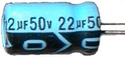
A standard radial capacitor.
A capacitor is generally used in an electronic circuit to filter out unwanted signals. The electrolytic capacitors in the DSM ECU are used to filter the power supply. An automobile is an extremely hostile place for electronics. The output of the alternator isn't all that pretty to begin with. Couple that with the spark plug high voltage firing, the radiator fans, the interior fan, turn signals going on and off... the +12VDC main power line gets a lot of crud on it.
Which capacitor to choose? There are a lot of different types out there - some large, some small, some really accurate, some "cleaner" for low noise pplications, etc. For power supply filtering, electrolytics are almost always used. Power supplies generally require a large capacitor to absorb spikes and dips. You can't afford not to have a steady power supply line inside of a computer - the microcontroller might act erratically or reboot. Electrolytics are chosen because they provide a lot of filtering for their small size. They are also very cheap.
The Problem[edit]
Electrolytic capacitors do have a downside, though. They tend to leak with age when exposed to heat and many power cycles. The electrolyte that leaks out is very harmful to PC boards. It can actually eat the copper traces, eventually making a short on the board. When that happens, the ECU will either stop working altogether or act very erratically. As the capacitor leaks, it will also lose its filtering properties, allowing possibly harmful spikes into the ECU.
Signs of Impending Doom[edit]
Luckily, there are usually some warning signs that your ECU is on its way out.
- A rapid clicking or chattering from under the dash. Usually accompanied with the engine stalling or losing power during the noise. This is the microcontroller going into reset over and over and over again due to a bad power supply. Every time it resets, it will turn the fuel pump relay on and off. This could also be a bad fuel pump relay, but not usually.
- An usual smell that seems to come from the center console. Especially if it smells like rotten seafood. Consider that it could also be your heater fan motor, unless accompanied with a power loss or stalling.
- Your car is older than seven years and sees a lot of extreme temperature transitions.
If you experience either of the first two problems above, act on them as soon as possible. Even though your car may still be drivable, the longer you let the problem go the more likely you will end up with a hole in your ECU's PC board or with several blown components on the board. Then you will have to dig a unit up in the junkyard or buy a new one from Mitsubishi for $1100.
The Solution[edit]
Purchase the Replacement Capacitors[edit]
|
|
Unfortunately, the particular capacitors you need can't be found at Radio Shack. They can be found at a Digi-Key, however.
- 47µF @ 50V (Digi-Key# P5570-ND)
- 22µF @ 50V (Digi-Key# P5568-ND)
- 100µF @ 25V (Digi-Key# P5540-ND)
By the way, in general, you can "up" either the voltage rating or the capacitance of the capacitor in a power supply application if you wish. For example, instead of 50V capacitors, you could use 63V capacitors. You just have to make sure that the body-style of the capacitor is "radial" (both leads coming out of the bottom, as opposed to "axial") and that it will fit.
|
Gather Supplies[edit]

|
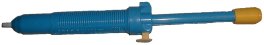
Although the instructions below are written for using copper solder braid and a solder sucker, we highly recommend using a professional desoldering station with its own air supply. A solder sucker and solder braid will do the job, but are much slower and not as accurate at the real thing. Make sure you have a good soldering iron with a large tip. You are also going to need some solder.
|
|
Remove the ECU[edit]
The first thing you will have to do is take the ECU out of the center console. ECU: Remove.
Remove the PC board from the case[edit]
Now would be a good time to put a grounding strap on your wrist, if you have one. Take the four screws out of the side of the case. Keep in mind that they might be incredibly tight. At least one usually is. Consider using a flat-blade screwdriver very carefully on the tough ones to allow for better torque. There are also four screws in the corners of the PC board itself. The same rule applies to those screws as you try to remove them.
Locate the Capacitors.[edit]
 Figure 1 - The Three Capacitors |
Figure 1 shows the positions of the capacitors and their values. You might want to inspect them for any sign of a leak or maybe a smoke trace if you've had a problem.
|
Add Solder to the Capacitors[edit]
|
|
Why do we want to add solder when we will just be sucking it away later? When the boards are wave soldered at the production factory, solder will attach to the capacitor leads on both the top side and bottom side of the thru-hole copper pad. It is possible that there is little or no solder in the hole between the top surface and the bottom surface. By adding solder back in, we assure ourselves there will be enough solder to conduct heat from the bottom of the board to the top of the board and melt the solder on the top surface of the pad. That will make sucking the solder out all that much easier and ensure that we won't be ripping the top off the pad when we take the capacitor out. Figure 2 shows solder being added to the 47µF capacitor. It also shows the position of all of the capacitor leads relative to the huge diode posts, which are unmistakably huge. Note that all of the capacitor legs are bent outwards while all resistor and diode leads are bent inwards.
|
Bend the Capacitor Leads[edit]
|
|
Now would be a good time to straighten out all of the capacitor leads. Figure 3 shows this being done with a tweezers while heat is applied with a soldering iron. This will make it easier to both solder suck and remove the capacitors later.
|
Suck the Solder[edit]
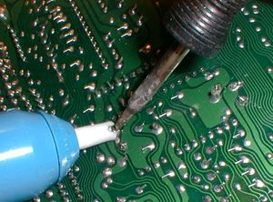 Figure 4 - Sucking the Solder |
Figure 4 shows the relatively mundane task of sucking out the solder. Make certain that the solder is nice and hot and is flowing well before you fire the trigger of the sucker. If you do it right, the solder will be sucked off the top layer of the board as well.
|
Clean the Pads[edit]
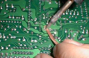 Figure 5 - Cleaning the Pads |
The hand-held manual solder sucker rarely gets all of the solder. Most of the time, you have to clean up after it. Figure 5 shows copper solder braid being used to sop up all of the residual solder to ensure a clean pull of the capacitor.
|
Pry out the Capacitors[edit]
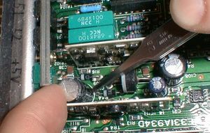 Figure 6 - Popping the Capacitor |
Using a tweezers or small screwdriver, carefully pry out the capacitors. If you encounter some resistance and it doesn't feel "right", you might want to go back and reclean the pads or go as far as adding back more solder and beginning the process again. Remember that you don't want to "pop" one of the thru-hole pads, or you will be doing some repair. Figure 6 shows the 47µF capacitor getting removed.
|
A Look at the Naked Board[edit]
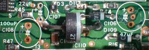 Figure 7 - Board without Capacitors |
Now that the capacitors are off, you should give them a good sniff. If any of them smell at all like rotten seafood, they are leaking. Be sure to pay attention to the area of the board underneath a leaking capacitor. For example, the ECU in these pictures had the faintest odor of rotten seafood from the 47µF capacitor. In Figure 7, notice that the bottom hole pad shows some darkness around the lower pad. It is the beginning of the oxidation of the copper pad. This ECU was caught just in time. Another thing that should be noticed in Figure 7 is the marked polarity of the hole pads. Inserting a capacitor "backwards" can lead to an explosion.
|
Install the Capacitors[edit]
 Figure 8 = Capacitor Polarity |
It is EXTREMELY IMPORTANT that you install the capacitors with the correct polarity. If you do not, the capacitors might explode, doing who knows what damage to the board. In Figure 8, on the capacitor, you can clearly see the negative sign inside of the arrow pointing to the lead that is negative. Note that the hole on the ECU PC board which the negative lead is going into is NOT marked with a "plus sign". Only the positive hole is marked on the ECU. Be sure to put the negative lead in the opposite hole. After you push the capacitor all the way down, take the leads on the bottom and bend them outward as they were from the factory. This will hold them in place for soldering.
|
Solder the Capacitors[edit]
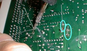 Figure 9 - Soldered Capacitors |
Downhill from here on out. Solder each of the capacitors as in Figure 9. Be sure to trim off the leads so there isn't a short.
|
Cleanup[edit]
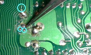 Figure 10 - Removing Solder Blobs |
Almost done! Check out the soldering job using a magnifying glass. Often, the solder will splatter a bit when using the solder sucker and solder braid. Use a fine tweezers as in Figure 10 to remove each small piece of solder or metal that represents a possible short. Then screw the PC board down into the bottom of the ECU case, put the cover on the ECU case, and you are ready to go!
|
©1998-2001 TechnoMotive
August 11th, 1998 Last updated May 18th, 2001


