Difference between revisions of "Tuning: Use MAF Translator Pro (MAFT Pro) as a Timing Monitor"
Stealthify (talk | contribs) (Created page with "Category:How To Category:Tuning '''MAFT Pro Timing Monitor Resistor Modification''' I don't recommend using the MAFT-pro as a timing monitor, because it requires cut...") |
Stealthify (talk | contribs) |
||
| Line 2: | Line 2: | ||
[[Category:Tuning]] | [[Category:Tuning]] | ||
| + | [[image:MaftProTiming01.jpg|thumb|400px]] | ||
| + | [[image:MaftProTiming02.jpg|thumb|400px]] | ||
| + | [[image:MaftProTiming03.jpg|thumb|400px]] | ||
'''MAFT Pro Timing Monitor Resistor Modification''' | '''MAFT Pro Timing Monitor Resistor Modification''' | ||
| Line 8: | Line 11: | ||
You can monitor timing for datalogging using this modification, BUT after doing this you can only use your MAFT Pro in speed density mode. | You can monitor timing for datalogging using this modification, BUT after doing this you can only use your MAFT Pro in speed density mode. | ||
| − | |||
| − | |||
| − | |||
This is the resistor that is cut to enable timing monitoring | This is the resistor that is cut to enable timing monitoring | ||
[[image:MaftProResistor.jpg|400px]] | [[image:MaftProResistor.jpg|400px]] | ||
| − | |||
Connect the yellow wire to pin 11 (power transistor A) | Connect the yellow wire to pin 11 (power transistor A) | ||
Latest revision as of 21:19, June 29, 2012
MAFT Pro Timing Monitor Resistor Modification
I don't recommend using the MAFT-pro as a timing monitor, because it requires cutting off a resistor on the circuit board. BEFORE you buy a MAFT-Pro used you need to make sure that this modification has not been done!
You can monitor timing for datalogging using this modification, BUT after doing this you can only use your MAFT Pro in speed density mode.
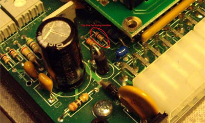
This is the resistor that is cut to enable timing monitoring
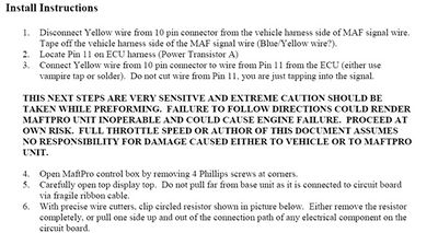
Connect the yellow wire to pin 11 (power transistor A)
The resistor you need to disconnect is shown in the above picture.
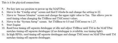
The F In Mode is set per the documentation, and the timing monitor will work. There are some settings to make it match your timing light or logger in the settings page.
There is a base and correction for the timing monitor in the settings page. the Base us used to make the idle match up, and the correction is used to fix the high RPM. There is some interaction, but its not too tough.


