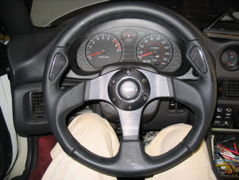
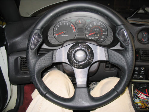
Steering: Replace Steering Wheel (Keeping Horn and Cruise Control)
Contents
Introduction[edit]
This how to is meant to show how to keep your cruise control and your horn after switching the stock steering wheel to a momo steering wheel. These instructions were performed on a 1991 Mitsubishi 3000GT VR4 so I can not guarantee you that they will transfer over exactly to any other year, however I would expect that they should be at least the same for all 1st generation VR4's and Stealth RT/TT's.
Disclaimer[edit]
As always I hold no responsibility if you in any way hurt your car and/or your self following these instructions.
Wiring Up The Horn[edit]
Step 1[edit]
Disconnect the battery
Step 2[edit]
After you have got the battery disconnected you need to find the connector under the steering wheel that comes off of the clock spring and carries the signals for the horn, cruise control, and radio controls. In order to see this connector you must first remove the lower dash panel above your knees. Please see these instructions on stealth316 and remove the piece that he refers to as the knee protector.
Step 3[edit]
You should now be able to look up right behind where the steering wheel comes down and you should see a 4 pin connector that has got the following color wires on each pin.
- Pin 1 = Yellow wire (radio control feedback)
- Pin 2 = Green wire (horn) - whenever this wire is grounded it will cause the horn to go off.
- Pin 3 = Blue wire (12v power used in both the cruise control circuit and the radio control circuit)
- Pin 4 = Black and White wire (cruise control feedback)
You can test and make sure that you have got the correct connector by disconnecting it and then reconnecting the battery and trying the horn. If the horn doesn't go off then you have found the right connector. Now disconnect the battery again and you can precede on.
Step 4[edit]
Now you need to remove the clock spring (has to be removed anyway to install the momo steering wheel). Then you need to cut the 4-pin connector that you found earlier to control the horn, cruise, and radio controls that was coming down from the clock spring. You will use this plug later. You can either do like I did and get a clock spring from a car that somebody is parting out and use the connector from it, or you can just cut the connector off of your factory clock spring. I just like to keep all of my factory parts in there original condition.
Step 5[edit]
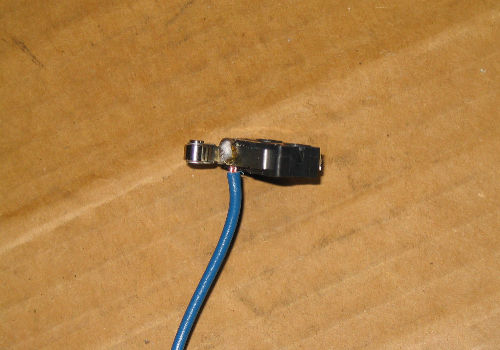
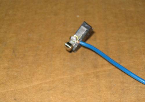
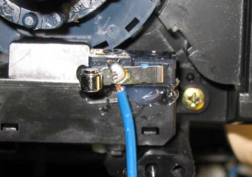
Now you need to purchase this switch from radioshack are some other electronics store. This switch will not actually be used as a switch, but the roller on the end will role against the metal ring on the back of the momo steering wheel hub adapter. Now find a piece of wire that is around a foot long and solder it to the part shown in the pictures below.
Step 6[edit]
Now you need to solder the end of this new wire coming off of the switch to the green wire coming off of the connector that you cut off from the clock spring earlier.
Step 7[edit]
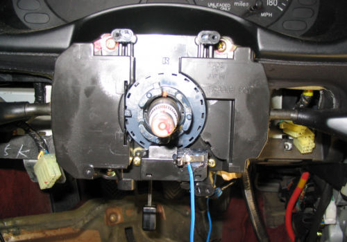
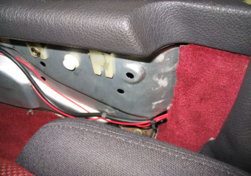
Now you need to mount the switch so that it will make contact with the metal ring on the back of the momo hub adapter. This will take a couple of tries most likely, but below are a couple of pictures of the way that I mounted it which seems to work great. I used a hot glue gun to mount it.
Once you mount the hub adapter and the new steering wheel you should now have a horn.
Wiring Up a Separate Cruise Control Panel[edit]
Basically the cruise control lever works by putting a different amount of resistance between two wires depending on which direction you push the leaver. This can be emulated using 3 momentary push buttons that can be purchased at any electronics store. The 3 different resistance and what they correspond to are listed below. No connection between the wires tells the computer that the switch is not being pushed in any direction.
- No resistance between the 2 wires equals the cancel option on the stock lever.
- 820 ohms of resistance between the 2 wires equals the resume / accelerate option.
- 2700 ohms of resistance between the 2 wires equals the set / coast option.
Step 1[edit]
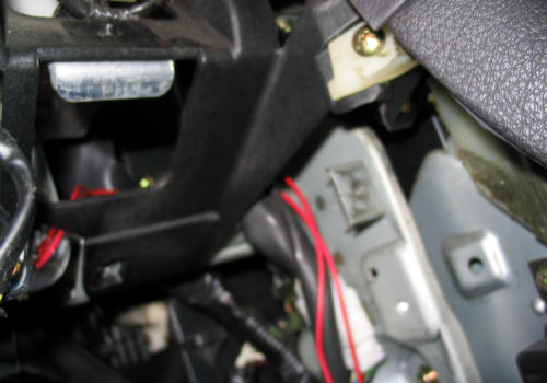
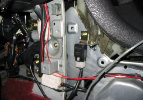
Solder in the 2 additional wires to the Blue wire and the Black/white wire that come off of the connector that you cut off earlier. These wires lengths will depend on where you want to put the push buttons. Once you have got these connections made you can connect the cut off plug back into it's mating connector under the steering column.
Step 2[edit]
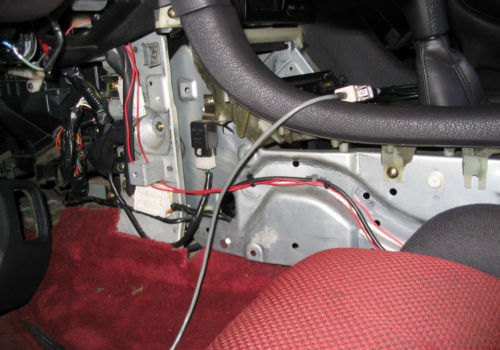
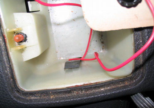
Route these wires to where ever you decided that you want the control panel to be. Since I never use the ash tray in my car I decided to make a black plexiglass cover that would go over it and mount the push buttons on that piece of plexiglass. Below is a few pictures of how I decided to mount the push buttons and route the wires.
Step 3[edit]
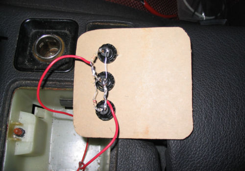
Now you need to solder these new wires in place. It does not matter which wire you connect to which side of the plug, the only thing that matters is that you do not connect the same wire to both sides of the plug. In order to get each of the push buttons to perform the function that you want wire in the proper resister listed above on one side of each of the push buttons. Below is a picture of what the bottom of the plexiglas panel looked like after I had finished wiring everything up.
Step 4[edit]
Now you just need to mount everything and connect the battery back up to test and make sure that everything works properly. If you have any questions please don't hesitate to PM me on 3si with the screen name andyvr4
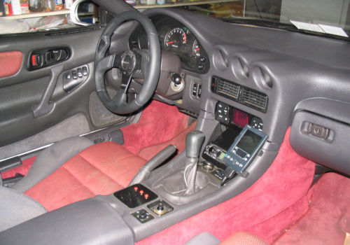
Pictures of my finished setup[edit]
This article was originally written by andyvr4.
